- Who we are
- Products
- FILLERS
- New Hyper Clean fillers
- HEVF - Electronic volumetric filling system
- HEMF - Electronic mass meter filling system
- HEVS - Electronic volumetric filling system for sparkling products
- HELC - filling system by level for carbonated products
- ELC - Micro brewery filling
- HRLF - Recirculation filling system
- Help Desk
- Media center
- News
- Contacts
- Careers

HEMF - Electronic mass meter filling system
FILLERS
New Hyper Clean fillers
HEVF - Electronic volumetric filling system
HEMF - Electronic mass meter filling system
HEVS - Electronic volumetric filling system for sparkling products
HELC - filling system by level for carbonated products
ELC - Micro brewery filling
HRLF - Recirculation filling system
HEMF - Electronic mass meter filling system
The filling machines of the renewed HEMF series, manufactured according to the new HYPER CLEAN characteristics, are suitable for the MASS filling of oil in PET bottles.
HEMF fillers are characterized by:
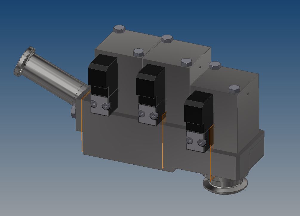
- high precision mass flow meter (flow meter that uses the Coriolis effect to determine the exact quantity of product at each passage) installed for each filling valve;
- simplified filling valve, with reduced number of gaskets, capable of managing two filling stages (slow filling and fast filling);
- special NO DROP filling valve, specifically designed for filling oil in PET bottles, with specific anti-drip function at the end of filling;
- no contact between filling valve and bottle during the filling;
- reduction of costs and time dedicated to maintenance of the filling valve.
The machine is complete, in the basic version, also with the following features:
- 7” HMI (15” HMI available as an optional);
- Parameters of each format to be directly managed through HMI;
- Quick changeover of the bottle guide equipment;
- Product pump to maintain constant pressure during filling;
- Compact frame for space saving in the filling line and reduced transport costs.
Available in various sizes to cover a wide range of production, the machines of the HEMF series are available in the filler/capper, rinser/filler/capper versions or in the innovative ECOBLOC® version where the ENOBERG filler-capper block is combined with the SMI stretch-blow moulder.
Advantages of filling with mass flow meters compared to filling by weight with load cells:
- Fast measurement with greater repeatability;
- No tare needed;
- No moving parts, in other words, no maintenance costs related to the flow meters;
- Valve monitoring and automatic compensation possible via PLC;
- No volume limit (the size of the bottle is not limited by the type of load cells);
- Greater stability and less calibration required on the flow meter lifecycle;
- Less impact of environmental conditions on the functioning of the flow meter (mechanical vibrations, agitation, splashes, etc).
PRODUCTION RANGE
PRODUCT | SPEED (bph) | REFERENCE |
Oil | 1.000 – 47.500 | 0.75 lt |
Oil in HC bottles | 1.000 – 6.200 | 5 lt |
OTHER DATA
Bottles capacity | 0.2 lt ÷ 12 lt (HC) |
Production speed | 1.000 ÷ 48.000 bph |
Filling valves | 9 ÷ 60 |
Workable caps | Plastic pressure cap |
Workable bottle diameter | 44 ÷125 mm (215 mm versione HC) |
Workable bottle height | 160 ÷ 340 mm |
Bottle handling | Neck Handling |
Operator panel | Touch screen 7" |

1INFEED CONVEYOR
PET bottles are transported inside the machine through an air conveyor. The bottle flow is regulated using a pneumatically operated gate which, depending on the condition of plant production, enables or blocks the bottles transfer to the first star wheel.
2BOTTLE TRANSFER: INLET - RINSER
Bottles coming from the air conveyor are transported towards the rinser. This transfer is performed through a rotating star wheel which receives the bottles from the air conveyor, handling them by the neck, and transports them towards the rinsing carousel.
3RINSER
The bottle coming from the star wheel reaches the rinsing turret where a rubber gripper grabs the bottle neck, and by using a mechanical cam system inverts the bottle (180 degrees) in order to have the bottle lip aligned with its rinsing nozzle. The nozzle is activated, dispensing water or air depending on the filling product and on the customers preference. At the end of the rinsing phase, the bottle is inverted again, coming back to the initial position.
The bottle is ready to be moved to the rinsing carousel. Each rinsing turret is equipped with a “no bottle-no spray" system: a sensor placed close to the rinser inlet detects the presence of the bottle. In the event that no bottle is detected, the correspondent turret will not perform any rinsing operation.
4BOTTLE TRANSFER: RINSER – FILLER
Bottles coming from the rinser are moved towards the filler. This transfer is performed through a rotating star wheel which collects the bottles from the rinsing turret, handling them by the neck, and transports them towards the filling carousel.
5FILLER
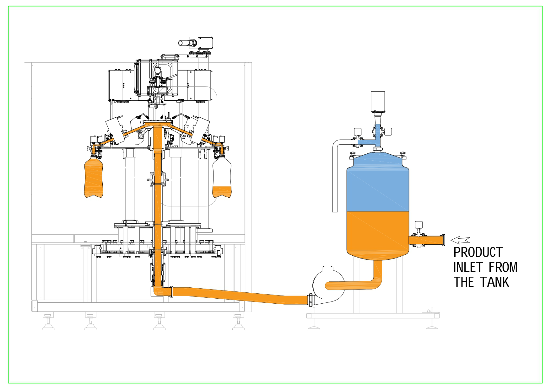
The bottle coming from the star wheel reaches the filling turret where a gripper grabs the bottle neck keeping it lined up under the filling valve. This filling technology does not involve the contact between valve and bottle. The filling product is contained in an external tank from which, through a pump, it is conveyed to the filling valves. The filling system is electronic volumetric with magnetic flow-meters (EVF models for conductive products) or electronic by mass with flow-meters based on the Coriolis principle (EMF models for non-conductive products). A gauge is connected to each filling valve. Once the movement has started, the gauge measures the quantity of product going through the valve. The counting method is pulse-based: when the set value is reached, a closure sign is sent to the filling valve.
The filled bottle is ready to be moved to the capping turret. Each filling turret is equipped with "no bottle-no fill" system: in the event that no bottle is detected in the filling turret, the filling operation will not start.
6BOTTLE TRANSFER: FILLER – CAPPER
Bottles coming from the filler are moved towards the capper. This transfer is performed through a rotating star wheel which collects the bottles form the filling turret, handling them by the neck, and transports them towards the capping turret.
7CAPPER
The bottle coming from the star wheel reaches the capping turret where a star shaped mould allows the bottle centering under the corresponding capping turret. The cap coming from caps feeding system is picked up by means of a star wheel called "pick and place". The capping head collects the cap from the star wheel and it applies the cap to the bottle. Depending on the cap to be applied (plastic screw cap or plastic pressure cap), the capping system may be rotating or by-pressure.
The rinsed, filled and capped bottle is ready to be moved to the outlet conveyor. Each capping turret is equipped with "no bottle-no cap" system: in the event that no bottle is detected under the capping turret, the cap will not be applied.
8OUTLET CONVEYOR
The rinsed, filled and capped bottles are transported out of the machine through an air conveyor. This conveyor is equipped with automatic height adjustment which allows the bottle point of support to be tailored to the bottle height.
TECHNICAL DATA
Advantages
- Modular structure which can be customized;
- Compact filling module which minimizes the number of stars for bottle handling, while ensuring an easy access for maintenance and cleaning;
- Modular framework which allows optimization of the shipping dimensions, cutting the transport costs and making the machine suitable for standard road transport;
- Low operating and maintenance costs;
- Low risk of contamination, high level of hygiene;
- Excellent price performance ratio.
Standard accessories
Each EVF/EMF machine is provided with:
- Independent movement of the machine axes through ICOS brushless motors with integrated control. Each motors parameter can be checked through HMI;
- Guarding in tempered glass;
- Dummy bottles installed in proximity to each filling valve;
- 7” HMI (Human Machine Interface) touch screen, supplied by SMITEC;
- Pre-programmed recipes, enabling quick changeover at a software level;
- Quick bottle changeover parts;
- Flow-meter installed in proximity to the filling valve;
- Easily serviceable filling valve, completely made in AISI 316;
- Electronic Filling system;
- Automatic cleaning phases (CIP).
Optional
Available on request, it is possible to install on ENOBERG’s EVF/EMF machine:
- Upper covering;
- Laminar flow to create an overpressure in the working environment and to prevent penetration of micro foreign objects in the machine;
- Sterile air blowing from the body of the filling valve during the filling;
- Automatic positioning dummy bottles;
- Components in contact with the product in AISI 316;
- Centrifugal caps sorter located outside the machine at the bottom, easily accessible for inspections and controls.
* The stated values are not binding, as they have to be confirmed by ENOBERG according to the user's production conditions.
Contact us
- ENOBERG S.r.l.
- Address: Via del Lavoro, 14
24060 Telgate BG
Italy - Phone: + 39 035 845908
- E-mail: info@enoberg.it
- Monday - Friday: 08:00 - 12:00 / 13:30 - 17:30
Saturday - Sunday: Closed
Privacy statement
TRANSPARENCY

![]()
Lawfulness of processing
All activities relating to personal data processing shall be lawful (consent, contract obligations, vital interests of the data subject or of third parties, compliance with legal obligations to which the controller is subject, public interest or exercise of official authority, legitimate interest pursued by the controller or by third parties).
![]()
Information statement
The information statement has been improved and updated to the new regulations (art. 13 and 14 GDPR).
![]()
Rights of the data subjects (right of access, right to erasure-right to be forgotten, right to restriction of processing, right to object, right to data portability)
Technical and organization measures have been adopted to ensure the data subject's exercise of his rights and to meet the data subject requirements.
![]()
Controllers, processors
Based on the new principle of “accountability”, SMI Group organization was re-defined, in order to proactively ensure integral compliance with the Regulation.
Redefinition of the role of data processors and service suppliers whose activity implies personal data processing.
![]()
Risk of data processing; accountability measures taken by controllers and processors (Impact assessment, record of processing activities, security of processing, data breach)
The “Conformity document”, including records of data processing activity, plans, adopts and demonstrates all technical and organizational measures taken to adequately perform the data processing activities and specifies the necessary procedures to be adopted to notify data breach.
![]()
Transfer of personal data to international organizations
Enoberg adheres to the general principles and guarantees concerning the transfer of personal data to third Countries.
The Controller is:
ENOBERG S.r.l.
Sede amministrativa: Via del Lavoro, 14 - 24060 Telgate (BG) - ITALIA
VAT.: 04471940165 - C.F.: 01490080163 - R.E.A.
For further information, write to: privacy@smigroup.net
According to the European Regulation 679/2016, the data subject is entitled to exercise the rights set forth in the Regulation.
The integral version of art. 15; 16; 17; 18; 20; 21; 77 of the European Regulation is attached to this document.
In order to exercise your rights, please send the application form duly filled in to the Controller's address.
Legal notice
ENOBERG S.R.L.
Società sottoposta a direzione e coordinamento da SMIGROUP S.p.A.
Società appartenente al GRUPPO IVA SMI INDUSTRIES
Sede amministrativa:
Via Carlo Ceresa, 10 - 24015 San Giovanni Bianco (BG) - ITALIA
Tel. +39 0345 40.111 - Fax: +39 0345 40.209 - www.enoberg.it
C.F. 01490080163 - P. IVA IT04471940165 - R.E.A. 210344
Iscr.Reg.Imprese 01490080163 - Cap. Soc. € 600.000 i.v.
Sede legale: Via Monte Grappa, 7 - 24121 Bergamo (BG) - ITALIA
Unità produttiva: Via del Lavoro, 14 - 24060 Telgate (BG) – ITALIA Tel. + 39 035 845908 - Fax: +39 0345 40 209


.jpg)


